???????????????????????????????????????
???????????????????????????????????????
????????????PWM????ADC??????
/**************************************************************************** * @file main.c * @version V2.0
* $Revision: 5 $ * $Date: 14/06/30 4:51p $ * @brief Demonstrate how to trigger ADC by PWM. * @note * Copyright (C) 2014 Nuvoton Technology Corp. All rights reserved. * ******************************************************************************/ #include <stdio.h> #include "NUC131.h" #define PLL_CLOCK 50000000 /*---------------------------------------------------------------------------------------------------------*/ /* Define Function Prototypes */ /*---------------------------------------------------------------------------------------------------------*/ void SYS_Init(void); //??????? void UART0_Init(void); //???????? void ADC_PWMTrigTest_SingleOpMode(void); //ADC??????????? void SYS_Init(void) //????????????�???????? { /*---------------------------------------------------------------------------------------------------------*/ /* Init System Clock */ /*---------------------------------------------------------------------------------------------------------*/ /* Enable Internal RC 22.1184MHz clock */ CLK_EnableXtalRC(CLK_PWRCON_OSC22M_EN_Msk); //??????RC??? /* Waiting for Internal RC clock ready */ CLK_WaitClockReady(CLK_CLKSTATUS_OSC22M_STB_Msk); /* Switch HCLK clock source to Internal RC and HCLK source divide 1 */ CLK_SetHCLK(CLK_CLKSEL0_HCLK_S_HIRC, CLK_CLKDIV_HCLK(1));//??? /* Enable external XTAL 12MHz clock */ CLK_EnableXtalRC(CLK_PWRCON_XTL12M_EN_Msk); /* Waiting for external XTAL clock ready */ CLK_WaitClockReady(CLK_CLKSTATUS_XTL12M_STB_Msk); /* Set core clock as PLL_CLOCK from PLL */ CLK_SetCoreClock(PLL_CLOCK); /* Enable UART module clock */ CLK_EnableModuleClock(UART0_MODULE); /* Enable ADC module clock */ CLK_EnableModuleClock(ADC_MODULE); /* Enable PWM0 module clock */ CLK_EnableModuleClock(PWM0_MODULE); /* Select UART module clock source */ CLK_SetModuleClock(UART0_MODULE, CLK_CLKSEL1_UART_S_HXT, CLK_CLKDIV_UART(1)); /* Select PWM01 module clock source */ CLK_SetModuleClock(PWM0_MODULE, CLK_CLKSEL3_PWM0_S_PCLK, 0); /* ADC clock source is 22.1184MHz, set divider to 7, ADC clock is 22.1184/7 MHz */ CLK_SetModuleClock(ADC_MODULE, CLK_CLKSEL1_ADC_S_HIRC, CLK_CLKDIV_ADC(7)); /*---------------------------------------------------------------------------------------------------------*/ /* Init I/O Multi-function */ /*---------------------------------------------------------------------------------------------------------*/ /* Set GPB multi-function pins for UART0 RXD and TXD */ SYS->GPB_MFP &= ~(SYS_GPB_MFP_PB0_Msk | SYS_GPB_MFP_PB1_Msk);//??????????? SYS->GPB_MFP |= SYS_GPB_MFP_PB0_UART0_RXD | SYS_GPB_MFP_PB1_UART0_TXD; /* Disable the GPA0 - GPA3 digital input path to avoid the leakage current. */ GPIO_DISABLE_DIGITAL_PATH(PA, 0xF);//????GPA0 - GPA3????????��???????��????? /* Configure the GPA0 - GPA3 ADC analog input pins */ SYS->GPA_MFP &= ~(SYS_GPA_MFP_PA0_Msk | SYS_GPA_MFP_PA1_Msk | SYS_GPA_MFP_PA2_Msk | SYS_GPA_MFP_PA3_Msk) ;//????GPA //0??PA3��?ADC??????????? SYS->GPA_MFP |= SYS_GPA_MFP_PA0_ADC0 | SYS_GPA_MFP_PA1_ADC1 | SYS_GPA_MFP_PA2_ADC2 | SYS_GPA_MFP_PA3_ADC3 ; //??????? /* Configure the PA12 as PWM0 output pin */ SYS->GPA_MFP = (SYS->GPA_MFP & (~SYS_GPA_MFP_PA12_Msk));//????PWM0?????? SYS->GPA_MFP |= SYS_GPA_MFP_PA12_PWM0_CH0;//PWM0??0??? } /*---------------------------------------------------------------------------------------------------------*/ /* Init UART */ /*---------------------------------------------------------------------------------------------------------*/ void UART0_Init()//??��??????????? { /* Reset IP */ SYS_ResetModule(UART0_RST); /* Configure UART0 and set UART0 Baudrate */ UART_Open(UART0, 115200); } /*---------------------------------------------------------------------------------------------------------*/ /* Function: ADC_PWMTrigTest_SingleOpMode */ /* */ /* Parameters: */ /* None. */ /* */ /* Returns: */ /* None. */ /* */ /* Description: */ /* ADC hardware trigger test. ADC???????????? */ /*---------------------------------------------------------------------------------------------------------*/ void ADC_PWMTrigTest_SingleOpMode()//????����?????? ???PWM????��???ADC???��????? { printf("\n<<< PWM trigger test (Single mode) >>>\n"); /* Set the ADC operation mode as single, input mode as single-end and enable the analog input channel 2 */ ADC_Open(ADC, ADC_ADCR_DIFFEN_SINGLE_END, ADC_ADCR_ADMD_SINGLE, 0x1 << 2); //??ADC??????????????????????????????????????????????2 ??ADC??? /* Power on ADC module */ ADC_POWER_ON(ADC); //#define ADC_POWER_ON(adc) ((adc)->ADCR |= ADC_ADCR_ADEN_Msk) //Before starting A/D conversion function, ADEN bit (ADCR[0]) should be set to 1.??????A / D??????????????ADEN��??ADCR [0]???????1?? /* Configure the hardware trigger condition and enable hardware trigger; PWM trigger delay: (4*10) system clock cycles*/ ADC_EnableHWTrigger(ADC, ADC_ADCR_TRGS_PWM, 0);//????????????????????????????; PWM??????????4 * 10????????????? /****************************************************************************************************************************************************** /* /** * @brief Configure the hardware trigger condition and enable hardware trigger.???????????????????????????? * @param[in] adc The pointer of the specified ADC module.adc???ADC??????? * @param[in] u32Source Decides the hardware trigger source. Valid values are: u32Source?????????????? * - \ref ADC_ADCR_TRGS_STADC :A/D conversion is started by external STADC pin.A / D???????STADC???????? * - \ref ADC_ADCR_TRGS_PWM :A/D conversion is started by PWM.//A / D?????PWM???? * @param[in] u32Param ADC trigger by external pin, this parameter is used to set trigger condition. Valid values are://u32Param ADC????????????? //?��???????????????????? * - \ref ADC_ADCR_TRGCOND_LOW_LEVEL :STADC Low level active. * - \ref ADC_ADCR_TRGCOND_HIGH_LEVEL :STADC High level active. * - \ref ADC_ADCR_TRGCOND_FALLING_EDGE :STADC Falling edge active. * - \ref ADC_ADCR_TRGCOND_RISING_EDGE :STADC Rising edge active. * @return None * @details Software should disable TRGEN (ADCR[8]) and ADST (ADCR[11]) before change TRGS(ADCR[5:4]). */ void ADC_EnableHWTrigger(ADC_T *adc, uint32_t u32Source, uint32_t u32Param) { ADC->ADCR &= ~(ADC_ADCR_TRGS_Msk | ADC_ADCR_TRGCOND_Msk | ADC_ADCR_TRGEN_Msk); ADC->ADCR |= u32Source | u32Param | ADC_ADCR_TRGEN_Msk; return; } *******************************************************************************************************************************************************/ /* Clear the A/D interrupt flag for safe */ ADC_CLR_INT_FLAG(ADC, ADC_ADF_INT);//???A / D?��??????????? /* Center-aligned type ?��?????PWM????????*/ PWM_SET_ALIGNED_TYPE(PWM0, PWM_CH_0_MASK, PWM_CENTER_ALIGNED);//???????????? /****************************************************************************************************************************************************** /** * @brief This macro set the PWM aligned type * @param[in] pwm The pointer of the specified PWM module * @param[in] u32ChannelMask Combination of enabled channels. Each bit corresponds to a channel. Every two channels share the same setting. * Bit 0 represents channel 0, bit 1 represents channel 1... * @param[in] u32AlignedType PWM aligned type, valid values are: * - \ref PWM_EDGE_ALIGNED * - \ref PWM_CENTER_ALIGNED * @return None * @details This macro is used to set the PWM aligned type of specified channel(s). * \hideinitializer */ #define PWM_SET_ALIGNED_TYPE(pwm, u32ChannelMask, u32AlignedType) \ do{ \ int i; \ for(i = 0; i < 6; i++) { \ if((u32ChannelMask) & (1 << i)) \ (pwm)->CTL1 = (((pwm)->CTL1 & ~(3UL << ((i >> 1) << 2))) | ((u32AlignedType) << ((i >> 1) << 2))); \ } \ }while(0)02 *************************************************************************************************************************************************************/ /* Clock prescaler ?????????*/ PWM_SET_PRESCALER(PWM0, 0, 1);//?��??????????????????? /******************************************************************************************************************************************************** /** * @brief This macro set the prescaler of the selected channel * @param[in] pwm The pointer of the specified PWM module * @param[in] u32ChannelNum PWM channel number. Valid values are between 0~5 PWM??? * @param[in] u32Prescaler Clock prescaler of specified channel. Valid values are between 1 ~ 0xFFF u32Prescaler??????????????????? // ??��???1?0xFFF??? * @return None * @details This macro is used to set the prescaler of specified channel. * @note Every even channel N, and channel (N + 1) share a prescaler. So if channel 0 prescaler changed, * channel 1 will also be affected. * \hideinitializer */ #define PWM_SET_PRESCALER(pwm, u32ChannelNum, u32Prescaler) (*(__IO uint32_t *) (&((pwm)->CLKPSC0_1) + ((u32ChannelNum) >> 1)) = (u32Prescaler)) ***********************************************************************************************************************************************************************/ /* PWM counter value */ /* PWM frequency = PWM clock source/(clock prescaler setting + 1)/(CNR+1) */ PWM_SET_CNR(PWM0, 0, 5);//?��????????????????? /**********************************************************************************************************************************************************
/**
* @brief This macro set the period of the selected channel
* @param[in] pwm The pointer of the specified PWM module
* @param[in] u32ChannelNum PWM channel number. Valid values are between 0, 2, 4. Every two channels share the same setting.
* @param[in] u32CNR Period of specified channel. Valid values are between 0~0xFFFF
* @return None
* @details This macro is used to set the period of specified channel.
* @note This new setting will take effect on next PWM period.
* @note PWM counter will stop if period length set to 0.
* \hideinitializer
*/
#define PWM_SET_CNR(pwm, u32ChannelNum, u32CNR) ((pwm)->PERIOD[(((u32ChannelNum) >> 1) << 1)] = (u32CNR))
/** * @brief This macro set the comparator of the selected channel * @param[in] pwm The pointer of the specified PWM module * @param[in] u32ChannelNum PWM channel number. Valid values are between 0~5 * @param[in] u32CMR Comparator of specified channel. Valid values are between 0~0xFFFF * @return None * @details This macro is used to set the comparator of specified channel. * @note This new setting will take effect on next PWM period. * \hideinitializer */ #define PWM_SET_CMR(pwm, u32ChannelNum, u32CMR) ((pwm)->CMPDAT[(u32ChannelNum)] = (u32CMR)) **********************************************************************************************************************************************************/ /* PWM compare value */ PWM_SET_CMR(PWM0, 0, 1); /******************************************************************************************************************************************************* /** * @brief This macro set the comparator of the selected channel ?��????????????????? * @param[in] pwm The pointer of the specified PWM module * @param[in] u32ChannelNum PWM channel number. Valid values are between 0~5 * @param[in] u32CMR Comparator of specified channel. Valid values are between 0~0xFFFF ????????u32CMR??????? ??��???0?0xFFFF??? * @return None * @details This macro is used to set the comparator of specified channel.?��??????????????????????? * @note This new setting will take effect on next PWM period.?????????????????PWM??????��?? * \hideinitializer */ #define PWM_SET_CMR(pwm, u32ChannelNum, u32CMR) ((pwm)->CMPDAT[(u32ChannelNum)] = (u32CMR)) ***************************************************************************************************************************************************************/ /* Enable PWM0 to trigger ADC */ PWM_EnableADCTrigger(PWM0, 0, PWM_TRIGGER_ADC_EVEN_PERIOD_POINT);//???PWM??????ADC /****************************************************************************************************************************************************** /** * @brief Enable selected channel to trigger ADC * @param[in] pwm The pointer of the specified PWM module * - PWM0 : PWM Group 0 * - PWM1 : PWM Group 1 * @param[in] u32ChannelNum PWM channel number. Valid values are between 0~5 * @param[in] u32Condition The condition to trigger ADC. Combination of following conditions: * - \ref PWM_TRIGGER_ADC_EVEN_ZERO_POINT * - \ref PWM_TRIGGER_ADC_EVEN_PERIOD_POINT * - \ref PWM_TRIGGER_ADC_EVEN_ZERO_OR_PERIOD_POINT * - \ref PWM_TRIGGER_ADC_EVEN_COMPARE_UP_COUNT_POINT * - \ref PWM_TRIGGER_ADC_EVEN_COMPARE_DOWN_COUNT_POINT * - \ref PWM_TRIGGER_ADC_ODD_COMPARE_UP_COUNT_POINT * - \ref PWM_TRIGGER_ADC_ODD_COMPARE_DOWN_COUNT_POINT #define PWM_TRIGGER_ADC_EVEN_ZERO_POINT (0UL) /*!< PWM trigger ADC while counter of even channel matches zero point */PWM????ADC???????????????????? #define PWM_TRIGGER_ADC_EVEN_PERIOD_POINT (1UL) /*!< PWM trigger ADC while counter of even channel matches period point */?????????????????????????PWM????ADC #define PWM_TRIGGER_ADC_EVEN_ZERO_OR_PERIOD_POINT (2UL) /*!< PWM trigger ADC while counter of even channel matches zero or period point */PWM????ADC?????????????????????????? #define PWM_TRIGGER_ADC_EVEN_COMPARE_UP_COUNT_POINT (3UL) /*!< PWM trigger ADC while counter of even channel matches up count to comparator point */??????????????????PWM????ADC????????????? #define PWM_TRIGGER_ADC_EVEN_COMPARE_DOWN_COUNT_POINT (4UL) /*!< PWM trigger ADC while counter of even channel matches down count to comparator point */PWM????ADC?????????????????????????????????? #define PWM_TRIGGER_ADC_ODD_COMPARE_UP_COUNT_POINT (8UL) /*!< PWM trigger ADC while counter of odd channel matches up count to comparator point */PWM????ADC??????????????????????????? #define PWM_TRIGGER_ADC_ODD_COMPARE_DOWN_COUNT_POINT (9UL) /*!< PWM trigger ADC while counter of odd channel matches down count to comparator point */PWM????ADC???????????????????????????? * @return None * @details This function is used to enable selected channel to trigger ADC. */ void PWM_EnableADCTrigger(PWM_T *pwm, uint32_t u32ChannelNum, uint32_t u32Condition) { if(u32ChannelNum < 4) { (pwm)->ADCTS0 &= ~((PWM_ADCTS0_TRGSEL0_Msk) << (u32ChannelNum * 8)); (pwm)->ADCTS0 |= ((PWM_ADCTS0_TRGEN0_Msk | u32Condition) << (u32ChannelNum * 8)); } else { (pwm)->ADCTS1 &= ~((PWM_ADCTS1_TRGSEL4_Msk) << ((u32ChannelNum - 4) * 8)); (pwm)->ADCTS1 |= ((PWM_ADCTS1_TRGEN4_Msk | u32Condition) << ((u32ChannelNum - 4) * 8)); } } *************************************************************************************************************************************************************/ /* PWM0 pin output enabled */ PWM_SET_OUTPUT_LEVEL(PWM0, PWM_CH_0_MASK, PWM_OUTPUT_HIGH, PWM_OUTPUT_NOTHING, PWM_OUTPUT_LOW, PWM_OUTPUT_NOTHING); /******************************************************************************************************************************************************* /** * @brief Set output level at zero, compare up, period(center) and compare down of specified channel(s) ????????????????????????????????????????????????? * @param[in] pwm The pointer of the specified PWM module // * @param[in] u32ChannelMask Combination of enabled channels. Each bit corresponds to a channel u32ChannelMask??????????????? ??��????????? * Bit 0 represents channel 0, bit 1 represents channel 1... * @param[in] u32ZeroLevel output level at zero point, valid values are: u32ZeroLevel?????????????��???? * - \ref PWM_OUTPUT_NOTHING * - \ref PWM_OUTPUT_LOW * - \ref PWM_OUTPUT_HIGH * - \ref PWM_OUTPUT_TOGGLE * @param[in] u32CmpUpLevel output level at compare up point, valid values are: u32CmpUpLevel???????????????��???? * - \ref PWM_OUTPUT_NOTHING * - \ref PWM_OUTPUT_LOW * - \ref PWM_OUTPUT_HIGH * - \ref PWM_OUTPUT_TOGGLE * @param[in] u32PeriodLevel output level at period(center) point, valid values are: ?????????????u32PeriodLevel??????????��???? * - \ref PWM_OUTPUT_NOTHING * - \ref PWM_OUTPUT_LOW * - \ref PWM_OUTPUT_HIGH * - \ref PWM_OUTPUT_TOGGLE * @param[in] u32CmpDownLevel output level at compare down point, valid values are: @param [in] u32CmpDownLevel??????????????????��???? * - \ref PWM_OUTPUT_NOTHING * - \ref PWM_OUTPUT_LOW * - \ref PWM_OUTPUT_HIGH * - \ref PWM_OUTPUT_TOGGLE * @return None * @details This macro is used to Set output level at zero, compare up, period(center) and compare down of specified channel(s). * \hideinitializer */ #define PWM_SET_OUTPUT_LEVEL(pwm, u32ChannelMask, u32ZeroLevel, u32CmpUpLevel, u32PeriodLevel, u32CmpDownLevel) \ do{ \ int i; \ for(i = 0; i < 6; i++) { \ if((u32ChannelMask) & (1 << i)) { \ (pwm)->WGCTL0 = (((pwm)->WGCTL0 & ~(3UL << (2 * i))) | ((u32ZeroLevel) << (2 * i))); \ (pwm)->WGCTL0 = (((pwm)->WGCTL0 & ~(3UL << (PWM_WGCTL0_PRDPCTLn_Pos + (2 * i)))) | \ ((u32PeriodLevel) << (PWM_WGCTL0_PRDPCTLn_Pos + (2 * i)))); \ (pwm)->WGCTL1 = (((pwm)->WGCTL1 & ~(3UL << (2 * i))) | ((u32CmpUpLevel) << (2 * i))); \ (pwm)->WGCTL1 = (((pwm)->WGCTL1 & ~(3UL << (PWM_WGCTL1_CMPDCTLn_Pos + (2 * i)))) | \ ((u32CmpDownLevel) << (PWM_WGCTL1_CMPDCTLn_Pos + (2 * i)))); \ } \ } \ }while(0) **********************************************************************************************************************************************************************************************************/ PWM_EnableOutput(PWM0, PWM_CH_0_MASK); /***************************************************************************************************************************************************** /* Start PWM module */ PWM_Start(PWM0, PWM_CH_0_MASK); /* wait for one cycle */ while(PWM_GetPeriodIntFlag(PWM0, 0) == 0); while(PWM_GetZeroIntFlag(PWM0, 0) == 0); PWM_ClearPeriodIntFlag(PWM0, 0); PWM_ClearZeroIntFlag(PWM0, 0); /******************************************************************************************************************************************************** /** * @brief Get period interrupt of selected channel ????????????????��? * @param[in] pwm The pointer of the specified PWM module * - PWM0 : PWM Group 0 * - PWM1 : PWM Group 1 * @param[in] u32ChannelNum PWM channel number. Valid values are between 0~5. Every two channels share the same setting. * @return Period interrupt flag of specified channel * @retval 0 Period interrupt did not occur * @retval 1 Period interrupt occurred * @details This function is used to get period interrupt of selected channel. */ uint32_t PWM_GetPeriodIntFlag(PWM_T *pwm, uint32_t u32ChannelNum) { return (((pwm)->INTSTS0 & (PWM_INTSTS0_PIF0_Msk << ((u32ChannelNum >> 1) << 1))) ? 1 : 0); } /** * @brief Get zero interrupt of selected channel ??????????????��? * @param[in] pwm The pointer of the specified PWM module * - PWM0 : PWM Group 0 * - PWM1 : PWM Group 1 * @param[in] u32ChannelNum PWM channel number. Valid values are between 0~5. Every two channels share the same setting. * @return zero interrupt flag of specified channel * @retval 0 zero interrupt did not occur * @retval 1 zero interrupt occurred * @details This function is used to get zero interrupt of selected channel. */ uint32_t PWM_GetZeroIntFlag(PWM_T *pwm, uint32_t u32ChannelNum) { return (((pwm)->INTSTS0 & (PWM_INTSTS0_ZIF0_Msk << ((u32ChannelNum >> 1) << 1))) ? 1 : 0); } /** * @brief Stop PWM generation immediately by clear channel enable bit * @param[in] pwm The pointer of the specified PWM module * - PWM0 : PWM Group 0 * - PWM1 : PWM Group 1 * @param[in] u32ChannelMask Combination of enabled channels. Each bit corresponds to a channel. * Bit 0 is channel 0, bit 1 is channel 1... * @return None * @details This function is used to stop PWM generation immediately by clear channel enable bit. ?��???????????????????��??????PWM??????? */ void PWM_ForceStop(PWM_T *pwm, uint32_t u32ChannelMask) { uint32_t i; for(i = 0; i < PWM_CHANNEL_NUM; i ++) { if(u32ChannelMask & (1 << i)) { (pwm)->CNTEN &= ~(1UL << ((i >> 1) << 1)); } } } /** * @brief Return the user-specified interrupt flags. ?????????????��????? * @param[in] adc The pointer of the specified ADC module. * @param[in] u32Mask The combination of following interrupt status bits. Each bit corresponds to a interrupt status.//u32Mask?????��???��?????? ???��???????��??? * Valid values are: * - \ref ADC_ADF_INT :Convert complete interrupt flag. * - \ref ADC_CMP0_INT :Comparator 0 interrupt flag. * - \ref ADC_CMP1_INT :Comparator 1 interrupt flag. * @return User specified interrupt flags. * @details Get the status of the ADC interrupt flag. */ #define ADC_GET_INT_FLAG(adc, u32Mask) ((adc)->ADSR & (u32Mask)) **************************************************************************************************************************************************************/ /* Stop PWM generation */ PWM_ForceStop(PWM0, PWM_CH_0_MASK); /* Wait conversion done */ while(!ADC_GET_INT_FLAG(ADC, ADC_ADF_INT)); /* Clear the ADC interrupt flag */ ADC_CLR_INT_FLAG(ADC, ADC_ADF_INT); printf("Channel 2: 0x%X\n", ADC_GET_CONVERSION_DATA(ADC, 2));//ADC?????????? /* Disable ADC */ ADC_POWER_DOWN(ADC); /********************************************************************************************************************************************************* ///** *??????ADC??� * @param [in] adc???ADC??????? * @?????? * @details????A / D?????????��????????? * @note?? */
#define ADC_POWER_DOWN??adc??????adc?? - > ADCR??=?ADC_ADCR_ADEN_Msk??
***********************************************************************************************************************************************************/
/*---------------------------------------------------------------------------------------------------------*/
/* MAIN function */
/*---------------------------------------------------------------------------------------------------------*/
int32_t main(void) { /* Unlock protected registers */
SYS_UnlockReg(); /* Init System, IP clock and multi-function I/O */
SYS_Init(); /* Lock protected registers */
SYS_LockReg(); /* Init UART0 for printf */
UART0_Init();
/*---------------------------------------------------------------------------------------------------------*/
/* SAMPLE CODE */
/*---------------------------------------------------------------------------------------------------------*/
printf("\nSystem clock rate: %d Hz", SystemCoreClock);
/* ADC hardware trigger test */
ADC_PWMTrigTest_SingleOpMode();
 /* Disable ADC module */
ADC_Close(ADC);
/* Disable ADC IP clock */
CLK_DisableModuleClock(ADC_MODULE);
/* Disable External Interrupt */
NVIC_DisableIRQ(ADC_IRQn);
printf("\nExit ADC sample code\n");
while(1);
}
???????????��??????????????????????????????????????????????????????
???????????????PWM??��???ADC??????????????????��??????????ADC?????????? PWM???????0??ADC???????2????????ADC???2???????????????PWM0??????ADC??????
void ADC_PWMTrigTest_SingleOpMode() { printf("\n<<< PWM trigger test (Single mode) >>>\n"); /* Set the ADC operation mode as single, input mode as single-end and enable the analog input channel 2 */ ADC_Open(ADC, ADC_ADCR_DIFFEN_SINGLE_END, ADC_ADCR_ADMD_SINGLE, 0x1 << 2);//??????????????????????????��????? /* Power on ADC module */ ADC_POWER_ON(ADC); /* Configure the hardware trigger condition and enable hardware trigger; PWM trigger delay: (4*10) system clock cycles*/ ADC_EnableHWTrigger(ADC, ADC_ADCR_TRGS_PWM, 0);//??????????? /* Clear the A/D interrupt flag for safe */ ADC_CLR_INT_FLAG(ADC, ADC_ADF_INT); /* Center-aligned type */ PWM_SET_ALIGNED_TYPE(PWM0, PWM_CH_4_MASK, PWM_CENTER_ALIGNED); /* Clock prescaler */ PWM_SET_PRESCALER(PWM0, 0, 1); /* PWM counter value */ /* PWM frequency = PWM clock source/(clock prescaler setting + 1)/(CNR+1) */ PWM_SET_CNR(PWM0, 0, 5); /* PWM compare value */ PWM_SET_CMR(PWM0, 0, 1); /* Enable PWM0 to trigger ADC */ PWM_EnableADCTrigger(PWM0, 0, PWM_TRIGGER_ADC_EVEN_PERIOD_POINT); /* PWM0 pin output enabled */ PWM_SET_OUTPUT_LEVEL(PWM0, PWM_CH_0_MASK, PWM_OUTPUT_HIGH, PWM_OUTPUT_NOTHING, PWM_OUTPUT_LOW, PWM_OUTPUT_NOTHING); PWM_EnableOutput(PWM0, PWM_CH_0_MASK); /* Start PWM module */ PWM_Start(PWM0, PWM_CH_0_MASK); /* wait for one cycle */ while(PWM_GetPeriodIntFlag(PWM0, 0) == 0); while(PWM_GetZeroIntFlag(PWM0, 0) == 0); PWM_ClearPeriodIntFlag(PWM0, 0); PWM_ClearZeroIntFlag(PWM0, 0); /* Stop PWM generation */ PWM_ForceStop(PWM0, PWM_CH_0_MASK); /* Wait conversion done */ while(!ADC_GET_INT_FLAG(ADC, ADC_ADF_INT)); /* Clear the ADC interrupt flag */ ADC_CLR_INT_FLAG(ADC, ADC_ADF_INT); printf("Channel 2: 0x%X\n", ADC_GET_CONVERSION_DATA(ADC, 2)); /* Disable ADC */ ADC_POWER_DOWN(ADC); while(1); }
PWM0??????????��?ADC2???????????
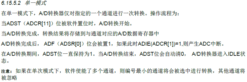
A/D??????????????????????(single)??????????��single-cycle scan?????????????(continuous scan mode)??A/D???????????????PWM??BPWM??????????STADC????????????
????????????????????????????


???????????????????????????????????????????????????????��??????????????1V????????????????????????0.1.??????????????1V??2V??????????????��???0.1?????????????????????????????�� ?????????????????????????????????????????????????????????????��????????????????????????????????????????????? ???��??????'??'????????????????'??'????????????????????????��???????????????????????????????????????????????????? ??????��?????????????????????????????????????????????��???????????????????????????????????????????? ???????????????????TI?????????ADC??????????????????????ADC????????????????????
????????
1.??STADC????????
2.??PWM????
??????????????
1.ADC_ADCR_TRGCOND_LOW_LEVEL
2.ADC_ADCR_TRGCOND_HIGH_LEVEL
3.ADC_ADCR_TRGCOND_FALLING_EDGE
4.ADC_ADCR_TRGCOND_RISING_EDGE
PWM_SET_OUTPUT_LEVEL???????????????
1.???????????
2.????????????? 3.????????????????????? 4.????????????????
??????????????????????????????????��??????????
??????????????????????ADC??TI???ADC??????16bit????��?????????????????AINP/AINN,?????????????????????
1?????????????????????????? ????????????? ?????ADC???????????????AINP - AINN,??????????????????????????????pad??????
???????????????? AINP - AINN
????????? AIN - REFN
2??????????????ADC??????????????????????
3????????????????????????????????????????????ADC????????????????????????????
PWM?��????ADC??????ADC?��????????????
?????????adc??????????????pwm?��????adc?????????????????????adc?��??????????????????????????????��????????????????
PWM????ADC?????????????
???????????????????????????????pwm?????ADC?????????????????????????PID??????
?????????????????1??
?????????????��??????
??????1????��????????????��??????��????????????????????????????????????????��? ????????????????????��??????��???��?��?????��????????
2??????????????????????????????
??1???????????
?????????????? ????????1??+9???????00001001??(????????+9????????????8��??2???????????????????????????????16��2?????????????????32��2???????????????)
??2???????????
????????��?1??????��???????????????��????????????????1?? ??????????????????????????????????????????-15???????8��2?????????11110001???????16��2??????????????????????1111111111110001??????????????????�p????????????????????????8��2?????????????????????????????????????????? ????????2????-7?????
?????????????????????????��???1????
????????��??+7?????0000111??????��?????1111000??????1??1111001??
????????-7???????11111001??
?????????????????????????????????????
??????1?????????????��???0?????????????????????????????
??????2?????????????��???1?????????????????????????????????????????????????
??????????????????????????
???????��??-15?????
???????????+15??00001111
?????????????��?????1???0??0???1??????????��??1??
????11110001
??????????????????????-64?????
????+64??01000000
????11000000
????????3?????????????11111001?????????10000111??-7????
???????????��???1???????????????????????��?????????1????
??????????��1111001??????0000110??
???????1????????10000111??
??????C????????????


972369124